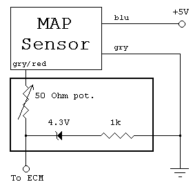
Yes it's true boys and girls! For a few bucks and a bit slight bit of effort on your part, you can build a circuit that when combined with a $2 wastegate bleed valve will give your Impulse RS the performance boost that those pathetic Hondaphiles spend hundreds on if not more to achieve. The circuit detailed here works to defeat the fuel cut mode that engages with the stock computer when boost exceeds 14 psi.
To date, the simple voltage divider attenuating circuit that I designed and installed on my RS has yielded nothing but thrills. Initial testing resulting in boost pressure reaching as high as 17 psi with no hint of the fuel cut mode engaging - or detonation for that matter. 200 shaft horsepower would be a conservative estimate at this point.
The best part about this is that anybody with a primitive knowledge of electronic circuit design and construction can build this particular circuit for less than 20 bucks - including a brand spankin' new soldering iron! The only electronic components needed are a 1k Ohm resistor, a 50-100 Ohm potentiometer, and a 4.3 Volt Zener diode. A few quick solders and a simple splice into the existing MAP Sensor wiring is all it takes from there.
This simple circuit is designed to allow minimal interruption of the MAP Sensor signal when operating at boost pressure below about 12 psi. When boost pressure exceeds 12 psi or the output from the MAP sensor reaches 4.3V, the Zener diode passes current to the 1k Ohm resistor, completing a low current voltage divider network that prevents the ouput voltage to the ECM from exceeding an adjustable threshold voltage that should ideally be set to just below the point where fuel cut should engage.
A more basic description is that it never lets the ECM know that the MAP Sensor has detected more than the fuel cut threshold.
The design of the circuit allows normal sensor operation at stock boost levels and below, and should not affect cold starting or 'open-loop mode' operation as long as excessive boost is not utilized until the engine warms up. The consequences of running high boost with this circuit on a cold engine are still unknown, but ya probably shouldn't be doing that sort of thing anyway.

I'd recommend using a generic printed circuit board and pcb type potentiometer. All of this can then be mounted inside a box smaller than a pager. For the prototype that I built, I drilled a hole in the exterior of the box so that I could adjust the potentiometer without disassembly. I would however recommend that the circuit be sealed from water by at least using electrical tape to cover the hole once adjusted.
This step is almost as easy as plugging in a stereo speaker. All you gotta do is tap the ground wire into the grey wire off of the MAP sensor. Then cut the grey/red wire and splice the FCE in series with it. Too easy!
My basic advice is to start with the potentiometer set to the lowest resistance and make successive high boost runs while incrementally increasing the resistance until the fuel cut mode no longer engages. Too much resistance could result in poor cold start performance and possibly a lean condition and detonation. (It may not be necessary to increase resistance at all - see below.)
Again, as a final note: The circuit presented and the modification of the MAP sensor signal in this way has been tested only on a very limited basis. I cannot guarantee that you will have the same results, but this design seems to be functioning as intended and has allowed me to run in excess of 15 psi with no apparent problems on 91 octane fuel. It may be possible to simplify the design by eliminating the potentiometer due to a voltage divider effect from the internal resistance of the MAP sensor, but I have yet to try it myself, and frankly don't feel the need to.
What you do with this information is your call. I hope that you find it useful.
If you build and install this circuit, let me know how it turns out!